|
 |
ISSN 1214-9675 Server vznikl za podpory Grantové agentury ČR. 21. ročník |
|
 |
ISSN 1214-9675 Server vznikl za podpory Grantové agentury ČR. 21. ročník |
|
Témata
Doporučujeme
Kontakt
|

Vydáno dne 06. 09. 2011 (14194 přečtení) |
 | (1) |
Some desired properties of these surfaces are:
 | (2) |
 | (3) |
Several surface classes (dependent on the choice of the blending functions Ni are used in com-puter graphics. Many of those are defined piecewise, i.e. the surface is constructed by defining smaller parts of the surface, called patches, each defined over a part of the domain which are then put together to form the total surface. The patches typically have rectangular or triangular domains. Triangular domains are sometimes preferred because they allow modelling surfaces with arbitrary polygonal domain (very polygon can be triangulated, but not all polygons can be build with rectangular domains).
In most cases the patches are defined over mutually exclusive domains and therefore cannot guarantee continuity along the patch boundaries in general. For triangular Bézier patches for instance the continuity has to be established by assuring that certain control points of adjacent patches are equal. If one wants to have a smooth connection between the patches (C1 continuous) one also has to place certain triples of control points at regular distance along one line.
DMS-splines were developed and first published in 1992 by W. Dahmen, C. A. Micchelim and H. P. Seidel; The name DMS is derived from the initials of their surnames [2], [5], [6], [7], [8], [9]. DMS-splines are functions that combine global smoothness of linear splines with the possibility of local control, thus the pleasant features of B-patches. DMS-splines are due to the complexity of their definition unattractive to conventional modelling. However, global smoothness makes them suitable for variable modelling because we do not achieve by adding restrictions to the location of control points. DMS-spline surface is like many other surfaces a weighted sum of control points. The weight of control points is given by blending function. DMS-splines as weighted functions use triangular spline functions. For DMS-spline surface of degree νi, each control point is weighted by triangular spline degree n and by multiplication constant. In order to define DMS-spline the domain triangular spline and other parameters need to define as well:
After we have provided these parameters, we can define a DMS-spline surface. Each control point cIβ is weighted by a simplex spline. The knotset of this simplex spline will contain n + 3 knots, hence the simplex spline will have degree n. The knotset of the simplex spline to weight cIβ consists of a union of pre fixes of knotclouds defined in the vertices of the triangle I. The closer cIβ lays to a vertex tj of I, the more knots are taken from the corresponding knotcloud. Formally we have as definition
|
| (4) |
To guarantee affine invariance and the convex-hull property of DMS-splines we have to show that
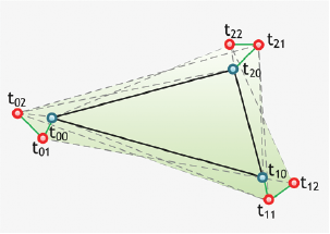
Figure 2: A single triangle I ∈I with its supports (green).
Quadratic DMS-spline functions have degree n = 2. The weights of control points, which depend on the evaluation point u, use quadratic triangular spline functions. In the non-generalized case of quadratic DMS-spline function, control points are a scalar value (r-coordinate).
Quadratic DMS-spline element is defined as contribution of one triangle (t00, t10, t20) of triangulation I to final DMS-spline function. Support of this element is a dedicated set of points V = {t00, t01, t02, t10, t11, t12, t20, t20, t22}. (See Fig. 2)
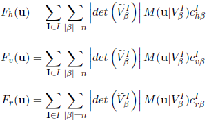
Quadratic DMS-spline element is defined as:
 | (5) |
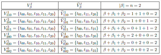
Table 1: Definition of quadratic triangular spline sets.
Number of quadratic triangular splines and number of control points is (n+1)(n+2)/2 = (2+1)(2+2)/2 = 6, from which 3 are placed near the vertices of triangle I after their orthographic projection to the plane (h, v). Control point, placed on vertex of the triangle, is called vertex control point and the one placed on the edge is called side control point. Figure 2 illustrates support of the triangle I interference to other triangles in the triangulation I at given vertex and knotclouds position.|
| (6) |
 | (7) |
 | (8) |

Figure 3: Conditions of normality - general. (Non-accepted positions)
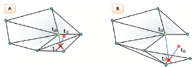
Figure 4: Conditions of normality - inside of triangulation. (No accepted positions)

Figure 5: Knotclouds placement for vertices ti0 on a triangulation border.
This method is enhancement of the heuristic univariate Monte Carlo algorithm [10]. This method has one degree of freedom, i.e. the distance of knots from the vertex ti0 which they belong to (with regard to additional conditions described herein before).
1. Find all triangle where vertex ti0 is one of triangular vertices (Fig. 6).
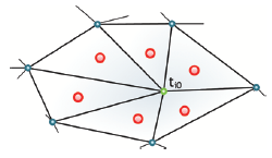
Figure 6: All triangles where vertex ti0 is one of its vertices. (red circles)
2. Determine two lines p1 and p2 passing trough vertex ti0 and axes of the largest angle α1 and the second largest α2 of these triangles. (Fig. 7, A)

Figure 7: Knotclouds placement technique for vertex ti0 inside the triangulation I.
3. Define lengths D1 and D2. Length D1 as approximately one third of shorter edge length d1 of triangle with the largest angle and with vertex ti0 and length D2 as approximately one third of shorter edge length d1 of triangle with the second largest angle and with vertex ti0. (Fig. 7, B)
4. Placement of knots ti1 and ti2 on line p1, resp. p2 in distance D1, respectively D2 rom vertex ti0 inside of the triangle with the largest angle, respectively second largest angle. (Fig. 7, C)
5. Check if conditions of normality for knotclouds are met. If not, then reduce distance (in case, if knots extend to other triangles supports, where vertex ti0 is one of triangle vertices), respectively change line p1 (p2) angle (in case, if knots are collinear with any vertex or one knot lay on the edge of a triangles). If after these steps, do not reached the conditions of normality over the whole triangulation, the triangulation is inconvenient and needs to control.
Next figure (Fig. 8) illustrates knotclouds ti1 and ti2 placement of vertex ti0. (Note: Connection between these points is only illustrative for better orientation in triangulation scheme.)
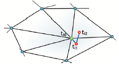
Figure 8: Knotclouds placement for vertex ti0 inside the triangulation I.
1. Find all triangles where vertex ti0 is one of triangle's vertices (Fig. 6). If there is only one triangle proceed to:
- Determine two lines p1 and p2 passing thought vertex ti0 and divide internal angel α by vertex ti0 to (1/3) α1 and (2/3) α2 (Fig. 9, A ). (Note: Order-independent)
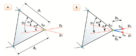
Figure 9: Determine of lines p1, p2 and edges d1, d2 single triangle.
- Define lengths D1 and D2 Length D1 as approximately one third of edge d1 length of triangle with vertex ti0 and closer to line p1. Length D2 as approximately one third of edge d2 length of triangle with vertex ti0 and closer to line p2. (Fig. 9, A).
- Placement of knots ti1 and ti2 on line p1, respectively p2 in distance D1, respectively. D2 from vertex ti0 outside of the triangle (outside of triangulation) (Fig. 9, B).
- Next, continue at step 5.
2. Determine external angle γ which contain triangles edges, where is ti0 one of vertices (Fig. 10).
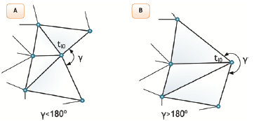
Figure 10: Determine of angle γ.
If external angle γ > 180° continue:
- Determine two lines p1 and p2 passing thought vertex ti0 and divide external angel γ to (1/3) γ1 and (2/3) γ2 (Fig. 10, A). (Note: Order-independent)
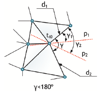
Figure 11: Determine of lines p1, p2 and edges d1, d2 (multiple triangles, angle γ > 180°).
- Define lengths D1 and D2. Length D1 as approximately one third of edge d1 length of triangle with vertex ti0 and closer to line p1. Length D2 as approximately one third of edge d2 length of triangle with vertex ti0 and closer to line p2 (Fig. 10, B).
- Next, continue to step 5.
3. Determine two lines p1 and p2 passing thought vertex ti0 and axes of the largest angle α1 and second largest α2 these triangles. (Fig. 12, A)
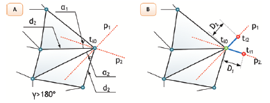
Figure 12: Determine of lines p1, p2 and edges d1, d2 (multiple triangles, angle γ < 180°).
4. Define lengths D1 and D2. Length D1 as approximately one third of shorter edge d1 length of triangle with vertex ti0 and largest angles. Length D1 as approximately one third of shorter edge d1 length of triangle with vertex ti0 and second largest angles. (Fig. 12, B)
5. Placement of knots ti1 and ti2 on line p1, respectively p2 in distance D1, respectively D2 from vertex ti0 outside of the triangle (outside of triangulation) (Fig. 2.10, B).
6. Check if all the conditions of normality for knotclouds are met are satisfy. If not, then reduce distance (in case, if knots extend to other triangles supports, where vertex ti0 is one of triangle vertices), respectively change line p1 (p2) angle (in case, if knots are collinear with any vertex or one knot lay on the edge of a triangles). If after these steps, conditions of normality are not fulfilled over the whole triangulation, the triangulation is faulty and needs to be corrected.
Next figure (Fig. 13) illustrates knotclouds ti1 and ti2 placement of vertex ti0. (Note: Connection between these points is only illustrative for better orientation in triangulation scheme.)
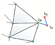
Figure 13: Knotcloud placement for vertex ti0 on the border the triangulation I.
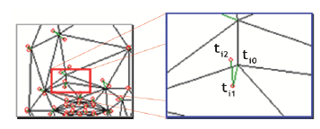
Figure 14: Triangulation with knotclouds placement. A: initial position of knots; B: Detail A - placement of knots ti1 and ti2 of vertex.
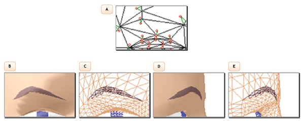
Figure 15: Initial position of knotclouds and approximated surface: A: left eyebrow area; B, C: approximated surface - front view filled (unfilled)triangulation after second interpolation and first DMS approximation with lighting and with averaging of normal vectors of particularly triangles. D, E: Approximation surface - left view filled (unfilled) triangulation after second interpolation and first DMS approximation with lighting and with averaging of normal vectors of particularly triangles.
Following figures (Fig. 16) show described affects of placement knotclouds.
- Type A: Triangulation a knotclouds placement ti1 and ti2 of vertex ti0.
- Type B: Approximated surface - front view filled triangulation after second interpolation and first DMS approximation with lighting and with averaging of normal vectors of particular triangles.
- Type C: Approximated surface - front view unfilled triangulation after second interpolation and first DMS approximation.
- Type D: Approximated surface - left view filled triangulation after second interpolation and first DMS approximation with lighting and with averaging of normal vectors of particularly triangles.
- Type E: Approximated surface - front view unfilled triangulation after second interpolation and first DMS approximation.
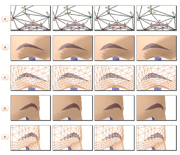
Figure 16: Example of displacement of knotclouds.
The following figure (Fig. 17) shows incorrect placement knot ti2 which interferes in support of triangle out of the area defined by triangles where vertex is one of vertices.
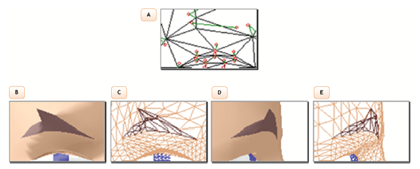
Figure 17: Example of incorrect knotclouds placement: A: left eyebrow area; B, C: approximated surface – front view filled (unfilled) triangulation after second interpolation and first DMS approximation with lighting and with averaging of normal vectors of particularly triangles. D, E: Approximation surface – left view filled (unfilled) triangulation after second interpolation and first DMS approximation with lighting and with averaging of normal vectors of particularly triangles.
Following figures (Fig. 18 and 19) show the example of using DMS-spline approximation with texture mapping. The CANDIDE 3-1-6 model used with texture of an attractive woman face, which is a research result at University of Regensburg [12] is shown in the folowing figures:
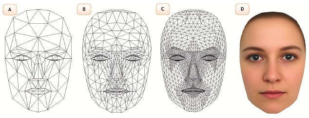
Figure 18: Process of approximation and texture mapping (front view). A: Basic triangulation; B: Control points mesh for quadratic DMS-surface; C: Approximated triangulation; D: Real human head texture mapped on a 3D model.
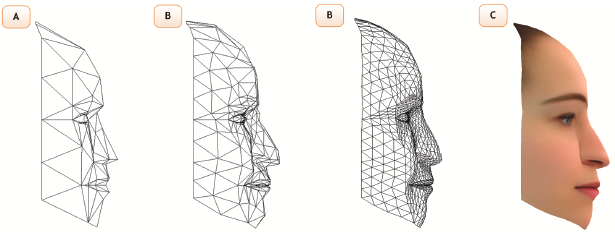
Figure 19: Process of approximation and texture mapping (left view). A: Basic triangulation; B: Control points mesh for quadratic DMS-surface; C: Approximated triangulation; D: Real human head texture mapped on a 3D model.
The main goal of this work was to propose an effective way of using the quadratic DMS-spline function to approximate surface area. The use of the quadratic DMS-spline function requires solving of automatic knotclouds and side control point placement. In this article I propose a solution for the problem of automatic knotclouds placement with regard to fulfillment of condition of normality over the whole triangulation. Furthermore, the article shows usage of DMS-spline function to approximate triangular mesh of CANDIDE 3-1-6 human head model. Proposed algorithm includes six steps which lead to the placement of knotclouds to the position to ensure normality of the whole triangulation with respect to surface smoothness.
Combination of global smoothness of linear splines and possibilities of local control of DMS-spline functions surface, seems to have good application in 3D model-based video coding. The possibility of local animation of human head surface model (CANDIDE 3-1-6 and/or M-4A) using FAP units (defined in MPEG-4) allows to apply DMS-spline approximation in model-based video coding. Furthermore, using DMS-spline functions improves the quality (more precisely approximation of real human head) and after enhancing local animation brings in addition flexibility and output video scenes increased computing speed.
This article has originated thanks to the support from the Ministry of Education, Youth and Sports of Czech Republic within the project MSM6840770014.
[1] Piegl L. and Tiller W. The NURBS Book. Springer-Verlag, 2nd edition, 1997.
[2] Dahmen W., Gasca M., and Micchelli Ch. A. Computation of curves and surfaces. Kluwer Academic Publisher, Netherlands, 1990.
[3] Žára J., Beneš B., Sochor J., and Felkel P. Moderní počítačová grafika. ISBN: 80-251-0454-0. Computer Press, a.s., 2nd edition, 2004.
[4] Dunn F. and Parberry I. 3D math primer for graphics and game development. Wordware Publishing, Inc, Los Rios Boulevard Plano, Texas, USA, 1st edition.
[5] Dahmen W. and Micchelli C. A. On the linear independence of multivariate B-splines, I. triangulations of simploids. SIAM Journal of Numerical Analysis, pages 993–1012, 1982.
[6] Dahmen W., Micchelli C. A., and Sedel H.-P. Blossoming begets B-spline bases built better by B-patches. Mathematics of Computation, 59:97–115, 1992.
[7] Fong P. and Seidel H.-P. An implementation of triangular B-spline surfaces over arbitrary triangulations. Computer Aided Geometric Design, 10:267–275, 1993.
[8] Greimer G. and Seidel P.-H. Modeling with triangular B-spline. Computer Graphics and Applications, IEEE, 1994.
[9] Feanssen M., Veltkamp R. C., and Wesselink W. Efficient evaluation of triangular B-spline surfaces. Computer Aided Geometric Design, 2000.
[10] Dahmen W., Gasca M., and Micchelli Ch. A. Multivariate splines: a new constructive approach. San Jose IBM. Research division, 1982.
[11] Rydfalk M. CANDIDE: A parameterized face. PhD thesis, University of Linkping, Sweden, 1978.
[12] Beautycheck - schonheit ist messbar!, 2007. http://www.beautycheck.de/, 07. 08. 2007. [on-line]
Tento web site byl vytvořen prostřednictvím phpRS - redakčního systému napsaného v PHP jazyce.
Na této stránce použité názvy programových produktů, firem apod. mohou být ochrannými známkami
nebo registrovanými ochrannými známkami příslušných vlastníků.